Three-Phase PLL Simulation
This interactive demonstration shows how a Phase-Locked Loop (PLL) works in power systems to track the phase angle of three-phase voltages, even during phase shifts and disturbances.
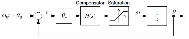
Basic structure of a Phase-Locked Loop
System Parameters
PLL Parameters
Three-phase voltages (Va, Vb, Vc)
Alpha-Beta components after Clarke transformation
Actual phase angle vs. PLL estimated angle
Real-time Measurements
Actual Phase Angle: 0°
PLL Estimated Angle: 0°
Angle Error: 0°
PLL Performance
Settling Time: 0 ms
Steady-state Error: 0°
Understanding PLL
What is a PLL?
A Phase-Locked Loop is an electronic system that locks the phase of an output signal to the phase of a reference signal. It keeps the output signal synchronized in frequency and phase with the input.
How it works
A Phase-Locked Loop (PLL) continuously compares the phase of an input signal with that of a voltage-controlled oscillator, and adjusts the oscillator's frequency through a filtered control voltage so that its output locks in phase and frequency with the input.
Why it matters
A Phase-Locked Loop matters because it allows electronic systems to stay perfectly synchronized, which is crucial for reliable communication, accurate timing, and stable signal processing.